


 Home /
 Custom Battery Pack for Thermal Imaging Cameras: Runtime and Pack Fit


Table of Contents
- Why a Custom Battery Pack for a Thermal Imaging Camera?
- Thermal-Camera Load Profile and Runtime
- Voltage, Capacity, and Pack Configuration
- Chemistry and Cell Format Trade-Offs
- Pack Fit: Mechanical and Electrical Integration
- Protection, BMS, Fuel Gauge, and Charging
- Prototype Validation and Production
- Documentation and Transport Requirements
- What to Send in an RFQ for a Custom Thermal-Camera Battery Pack
- Start the Conversation with Your Camera’s Requirements
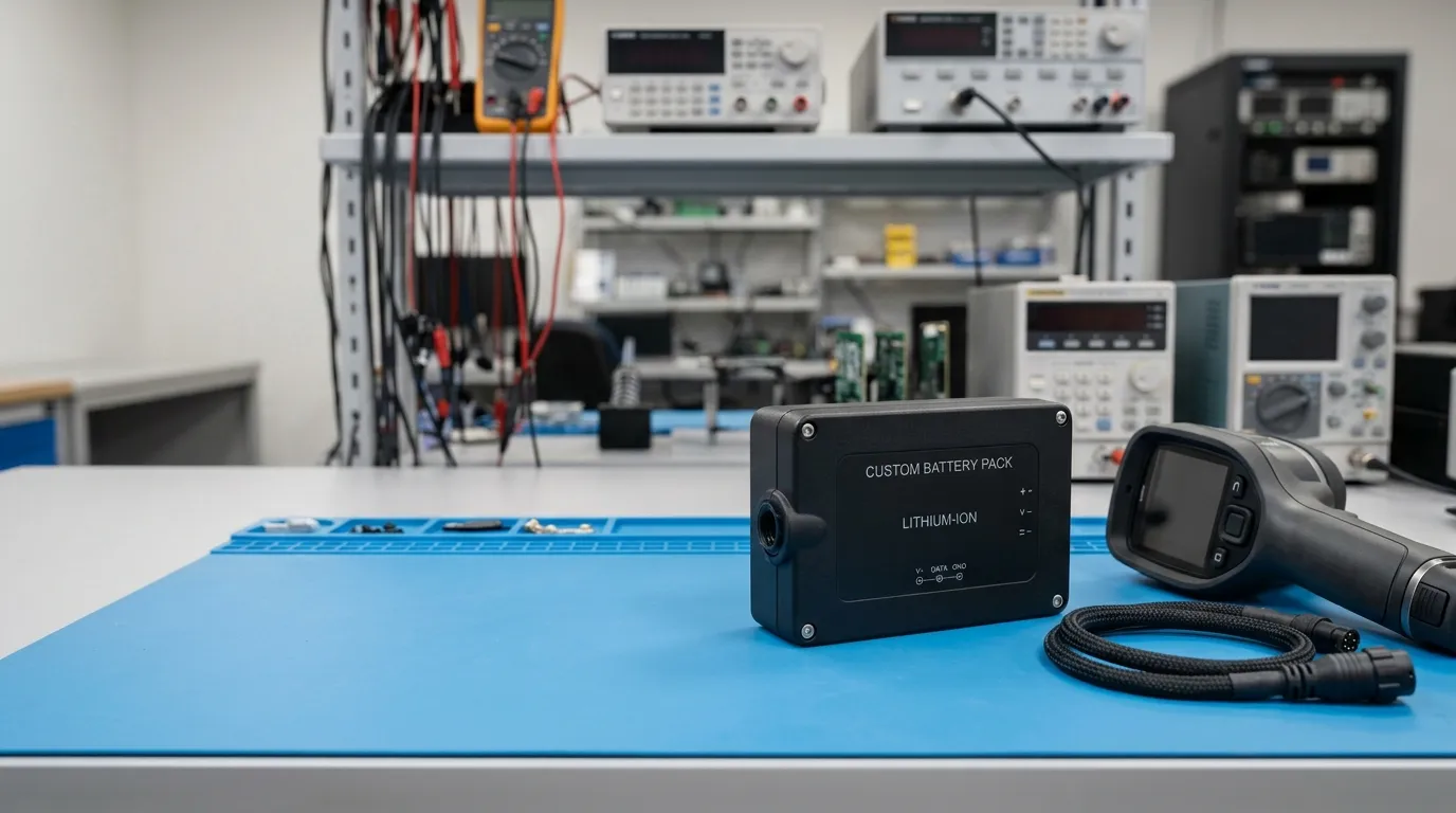
A custom battery pack for a thermal imaging camera is sized from the camera’s actual voltage and load requirements, then constrained by target runtime, physical envelope, connector and charger interface, operating temperature, BMS protection, and the validation or transport documents required for the finished product. Unlike a catalog replacement, a custom pack is engineered around the camera’s measured behavior, not just its model number.
Thermal imaging cameras present a specific power challenge. A handheld unit may draw steady power for the display and sensor, but it can also demand sudden current peaks when the processor accelerates, the wireless module transmits, or the illuminator fires. A pack that fits the battery compartment but cannot sustain those peaks may shut down with charge remaining. A custom pack design starts with the camera’s real load profile and then balances energy, current capability, mechanical fit, charging, and protection against the enclosure space available.
Why a Custom Battery Pack for a Thermal Imaging Camera?
A custom pack becomes necessary when a standard replacement does not meet one or more of the following requirements:
- Physical fit. The battery compartment may have an unusual shape, a specific connector, a required cable exit, or a mounting constraint that a stock pack cannot satisfy.
- Runtime. The camera’s operating modes may draw more current than a standard pack’s capacity supports for the required shift or mission duration.
- Current capability. Startup, transmission, illumination, or processing peaks can cause voltage sag if the pack’s cell configuration and internal resistance are not matched to the load.
- Operating environment. Firefighting, industrial inspection, outdoor surveillance, and cold-weather use place different demands on chemistry, BMS protection, thermal management, and enclosure design.
- Charging and protection. The pack’s charge profile, connector, and BMS thresholds must match the camera’s charging system and protection expectations.
- Documentation and validation. OEM production requires datasheets, test evidence, and transport documentation that consumer replacement packs rarely provide.
When a camera is being developed or redesigned, the battery pack becomes part of the system engineering, not an aftermarket accessory.
Thermal-Camera Load Profile and Runtime
Runtime cannot be calculated from capacity alone. The camera’s load profile defines how much current the pack must deliver over time, how high the peaks rise, and how often they occur.
A thermal camera’s load profile typically includes:
- the display and backlight;
- the sensor and image-processing electronics;
- the wireless or data-transmission module;
- the infrared illuminator or laser pointer, when active;
- the processor under heavy image-analysis load.
The average current determines the energy draw and therefore the runtime. The peak current determines whether the pack can support momentary demand without excessive voltage sag.
A battery’s capability to deliver current is described in part by its C-rate, which normalizes current against capacity. A 5 Ah pack discharged at 1C delivers 5 A continuously. At 2C, it delivers 10 A. The higher the C-rate demand, the more important cell selection, internal resistance, and pack configuration become.
Voltage sag is the drop in pack voltage that occurs under load, driven largely by internal resistance. If sag pulls the pack below the camera’s cutoff voltage, the camera may shut down even though the pack still contains charge. That behavior is a common complaint with under-specified replacement packs.
Runtime Calculation Example
A worked example shows how the numbers fit together. The values below are illustrative, not a Gloflux specification.
| Parameter | Value |
|---|---|
| Average camera current draw | 3.5 A |
| Peak current draw | 6.5 A |
| Target runtime | 4 hours |
| Pack nominal voltage | 11.1 V (3S configuration) |
| Required energy | 3.5 A × 4 h × 11.1 V ≈ 155 Wh |
At 11.1 V nominal, 155 Wh corresponds to roughly 14 Ah of capacity. A pack in that range would need multiple parallel cells, which directly affects physical size, mass, and cell matching.
The calculation assumes a stable average current at nominal voltage, but real conditions differ. Low temperature raises internal resistance, older cells lose capacity, and the camera’s software may draw more current under processing load. A custom design should include margin for those factors rather than treating the arithmetic as a guarantee.
Voltage, Capacity, and Pack Configuration
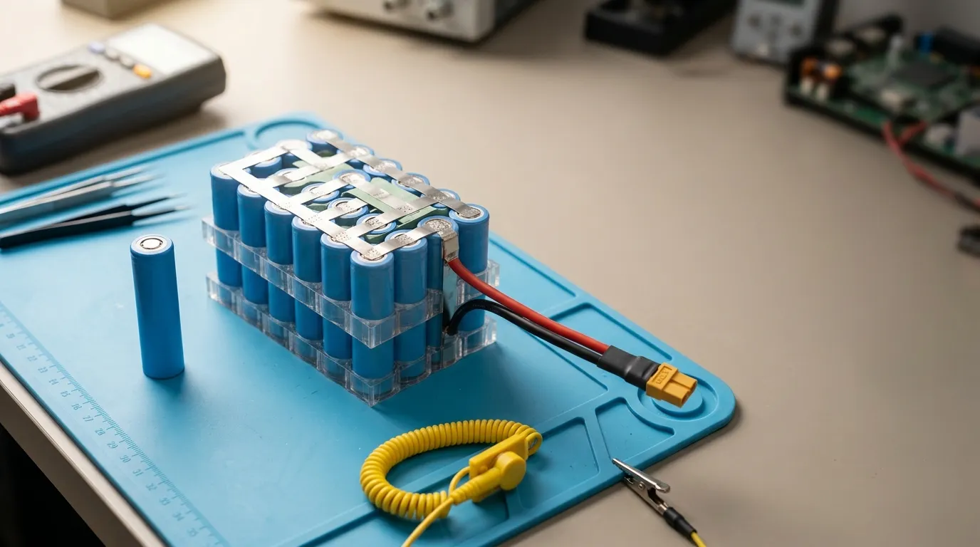
The camera defines a voltage window. The pack must operate within that window under all load conditions, including the voltage sag that occurs at peak current.
Nominal voltage is the pack’s rated midpoint, determined by the series cell count. A 3S lithium-ion pack has a nominal voltage of 11.1 V and a maximum charge voltage of 12.6 V. The maximum charge voltage matters because the charger must be matched to it. Using a charger designed for a different chemistry or series count can overcharge the pack.
Capacity in mAh or Ah describes charge quantity. Energy in Wh describes total deliverable energy and is the more meaningful measure for both runtime comparison and lithium-battery transport documentation. A 10 Ah pack at 11.1 V stores approximately 111 Wh. A 10 Ah pack at 14.8 V stores approximately 148 Wh. The same capacity number can represent very different energy content depending on voltage.
Pack configuration is expressed as series (S) and parallel (P) counts:
- Series count determines voltage.
- Parallel count determines capacity and current capability.
Each parallel group must contain matched cells to avoid imbalance and premature aging. The physical result of more parallel groups is a larger and heavier pack, which creates the fit challenge.
Chemistry and Cell Format Trade-Offs
The chemistry and cell format influence voltage, energy density, operating temperature, cycle life, safety characteristics, and the physical shape of the pack.
| Chemistry | Nominal Voltage per Cell | Common Strengths | Typical Trade-Offs |
|---|---|---|---|
| Lithium-ion (Li-ion) | 3.6–3.7 V | High energy density, established supply chain, wide availability in cylindrical formats such as 18650 and 21700 | Requires protection circuitry; thermal runaway risk under abuse; capacity degrades at temperature extremes |
| Lithium-polymer (Li-polymer) | 3.7 V | Flexible pouch format supports custom shapes and thin enclosures; lighter enclosure options | Lower volumetric energy density than some cylindrical cells; softer cell requires mechanical protection and swelling allowance |
| Lithium iron phosphate (LiFePO4) | 3.2–3.3 V | Lower thermal-runaway risk, long cycle life, better tolerance to abuse conditions | Lower nominal voltage and lower energy density; may require a different series count and charger profile |
Li-polymer’s advantage is fit. A camera enclosure with a curved or shallow cavity may not accept a cylindrical cell pack, whereas a pouch cell can be shaped around the available space. Li-polymer is a strong candidate when enclosure volume is tight and the pack can be designed around the cavity from the start.
LiFePO4 is not a default choice for a handheld thermal camera. Its lower nominal voltage also means that the midpoint and cutoff voltages differ from a Li-ion pack, which affects BMS thresholds and charger compatibility. It only becomes attractive when safety risk, cycle life, or abuse tolerance outweighs the energy-density penalty.
Li-ion cylindrical cells remain a practical choice when the enclosure accepts a rectangular or cylindrical pack layout, because the cell formats are widely available, well-characterized, and supported by extensive test data.
No single chemistry is universally superior. The correct choice depends on the camera’s voltage window, enclosure, runtime target, operating temperature, and expected lifecycle.
Pack Fit: Mechanical and Electrical Integration
Pack fit is more than dimensions. The complete electro-mechanical interface must match the camera and its charging system.
Key fit considerations include:
- Dimensions and shape, including clearance for cell swelling in pouch packs and room for BMS, wiring, and insulation;
- Mass and balance, which affect handheld ergonomics and gimbal or drone suitability where relevant;
- Connector type, polarity, and retention, which must match the camera’s mating connector and lock mechanism;
- Cable exit and wire gauge, which must carry the expected current without excessive voltage drop;
- Mounting, whether the pack is screwed, clipped, or held by the enclosure;
- Enclosure material and ingress protection, with an IP rating stated precisely rather than described as “waterproof”;
- Thermal path, because the pack may need to dissipate heat in a sealed cavity or operate in an already hot environment;
- Service access, if the pack must be replaceable by an end user.
An IP rating is a specific, tested standard. A pack that is splash-resistant is not necessarily waterproof. If an ingress rating matters, it must be specified and tested against the correct standard, not claimed casually.
Connector selection also affects charging. If the pack charges through the same connector used for discharge, the system must handle the charging current safely. If charging happens through a separate port or an external cradle, the wiring, terminals, and BMS must match each interface.
For OEM development, the pack should be designed against a 3D envelope and electrical interface specification, not against a photograph or a competitor’s replacement listing.
Protection, BMS, Fuel Gauge, and Charging
Every lithium battery pack needs protection against overcharge, over-discharge, overcurrent, short circuit, and excessive temperature. The question is how much beyond basic protection the camera requires.
- PCM (protection circuit module) provides basic protection functions. It is suitable when the camera and charger handle all higher-level battery management themselves.
- BMS (battery management system) adds control and coordination, including cell balancing, state-of-charge estimation, protection thresholds, and potentially communication with the host device.
- Smart BMS with fuel gauge estimates remaining runtime and state of charge. This is directly relevant to a thermal camera, where the operator needs to know whether the unit will last through the shift.
A fuel-gauge function may use a communication interface such as SMBus, I2C, UART, CAN, RS485, or Bluetooth. The protocol must be supported by the camera’s firmware. A fuel gauge that the camera cannot read provides no operational benefit.
Cell balancing is required for any multi-cell series pack. Without balancing, small differences in cell capacity or self-discharge grow over time, reducing usable capacity and cycle life.
Charging must match the pack’s chemistry and series count. A Li-ion pack charged with a LiFePO4 charger will be undercharged. A LiFePO4 pack charged with a Li-ion charger will be overcharged and may be damaged or become unsafe. The charge current, termination voltage, and temperature limits all matter.
Low-temperature charging is a specific risk for lithium-ion packs at or below freezing. Many chemistries restrict or prohibit charging below 0 °C. If the camera will be charged in cold environments, that requirement must be part of the specification.
Prototype Validation and Production
A prototype confirms that the pack actually meets the requirements. Validation must test real conditions, not paper specifications.
Typical prototype acceptance checks include:
- Capacity test, measuring actual delivered capacity under a defined discharge rate and temperature;
- Runtime test, using the camera’s actual load profile rather than an idealized constant current;
- Voltage-sag test, recording pack voltage during peak-current events to confirm the pack stays above the cutoff threshold;
- Mechanical fit test, confirming the enclosure, connector, wiring, and mounting work exactly as designed;
- Thermal test, checking that the pack and camera remain within temperature limits during sustained operation or charging;
- Charging test, verifying charger compatibility, termination, and protection behavior;
- Fuel-gauge calibration, if a smart BMS is included.
After prototype approval, a pilot production run verifies that the cells, BMS, assembly process, and quality controls produce consistent packs. Traceability matters in production: the OEM should be able to trace cells, BMS, and assembly records for each pack, and receive change notifications when a component or process changes.
Gloflux follows this type of structured process for custom battery development. According to its published workflow, the company covers [custom battery design](), cell sourcing, engineering design, prototype testing, mass production, and after-sales service for OEM customers. This workflow is the same foundation used to support a variety of industrial and application-specific battery solutions, including wide temperature lithium ion battery pack options and lithium battery quality control and testing procedures.
Documentation and Transport Requirements
Lithium battery packs shipped worldwide are subject to transport regulations. A UN38.3 test summary is required for lithium cells and batteries transported by air under current regulations. The test summary documents the cell or battery type, watt-hour rating or lithium content, the tests completed, and the pass/fail results.
According to the U.S. Department of Transportation’s Pipeline and Hazardous Materials Safety Administration (PHMSA), the test summary must be made available to downstream customers and air carriers, and it must include the manufacturer, test laboratory, and test results in a defined format. PHMSA provides an official lithium battery test summary form that shows exactly which fields are required. That document is a good template for understanding what a supplier should provide.
A UN38.3 test summary is not a product-safety certificate. It confirms that a specific cell or battery design passed transport tests. Safety certification, such as an IEC 62133 or UL report, is a separate matter that applies only to the exact model and construction covered by the report. The two documents are often confused.
An OEM should expect the following from a responsible battery supplier:
- a battery datasheet (TDS) with exact electrical, mechanical, and environmental specifications;
- a safety data sheet (SDS/MSDS) where applicable;
- a UN38.3 test summary for the exact cell and pack design;
- any model-specific IEC/UL/CB or other certification reports that exist;
- CE, RoHS, REACH, or other declarations only where applicable;
- clear identification of which certificates apply to which model, batch, and legal entity.
A company-level quality certificate, such as ISO 9001, describes the company’s quality management system. It does not certify a specific battery pack. The distinction matters when evaluating documentation.
For OEM production, each pack should be traceable to its cell lot, BMS batch, assembly record, and test results. A supplier that cannot provide product-level documentation and traceability cannot support regulated market entry or reliable field service.
What to Send in an RFQ for a Custom Thermal-Camera Battery Pack

A well-structured RFQ saves time and improves the quality of the supplier’s proposal. The more precise the requirements, the more relevant the design, testing, and quotation will be.
| Requirement Category | What to Provide |
|---|---|
| Electrical | Nominal and maximum charge voltage for the camera; load profile with average and peak current; voltage cutoff; charging method and charger voltage/current |
| Runtime | Target runtime in hours under defined operating conditions; whether the runtime includes continuous transmission, illumination, or heavy processing |
| Mechanical | Available enclosure space with a 3D model or drawing; connector type and pinout; cable exit direction and length; mounting method; mass limit |
| Environmental | Operating, charging, and storage temperature range; IP rating requirement; exposure to moisture, vibration, or impact; outdoor or indoor use |
| Integration | Required BMS or fuel-gauge features; communication protocol; any firmware or hardware interface requirement for the battery |
| Compliance | Target markets; required certifications; transport destinations; whether a UN38.3 test summary or model-specific certificate is required |
| Commercial | Estimated annual volume, prototype quantity, target production date, required documentation, and any labeling or packaging requirements |
Sending a complete RFQ also signals that the buyer understands the product. It shortens the back-and-forth between the OEM and the battery supplier and shifts the conversation toward engineering and validation rather than specification discovery.
For a Lithium battery for laser measurement devices, the constraints are similar because both applications require portable, reliable power with predictable runtime in field conditions. The same RFQ structure applies.
Start the Conversation with Your Camera’s Requirements
A custom thermal-camera battery pack succeeds when it is specified from real measurements, not assumptions. The load profile, voltage window, physical envelope, connector, charging interface, operating environment, and required documentation all matter. A supplier that receives that information can design, prototype, test, and validate a pack with confidence.
If you are at the specification stage, prepare the RFQ checklist above and share it with Gloflux. The custom battery design process starts with your requirements and moves through cell selection, pack engineering, prototyping, validation, and production. Provide the load profile, enclosure space, runtime target, and documentation needs, and the Gloflux engineering team can begin a feasibility review for your thermal imaging camera.
Talk to the Manufacturer
Resources & Insights

High Capacity Lithium Battery for Wearables: High-Voltage LiPo Cell Design
2026-10-19
Cylindrical Battery Packs for Laptops: 2S vs 3S vs 4S Battery Design
2026-10-19
Stage Lighting Battery Pack: Prevent Voltage Drop & LED Flicker
2026-10-19

Best Rechargeable Batteries for Smart Devices: Performance, Safety, and Selection Guide
2026-10-19


