


 Home /
 Rechargeable Battery for Delivery Robots: Runtime and Charging Design


Table of Contents
- How to Estimate Runtime for a Delivery Robot
- Choosing the Delivery-Robot Battery Chemistry
- Designing the Battery Pack Architecture
- Designing the Charging System for Fleet Uptime
- Validating the Battery Before Deployment
- Preparing the Delivery-Robot Battery RFQ
- Common Mistakes to Avoid When Specifying a Delivery-Robot Battery
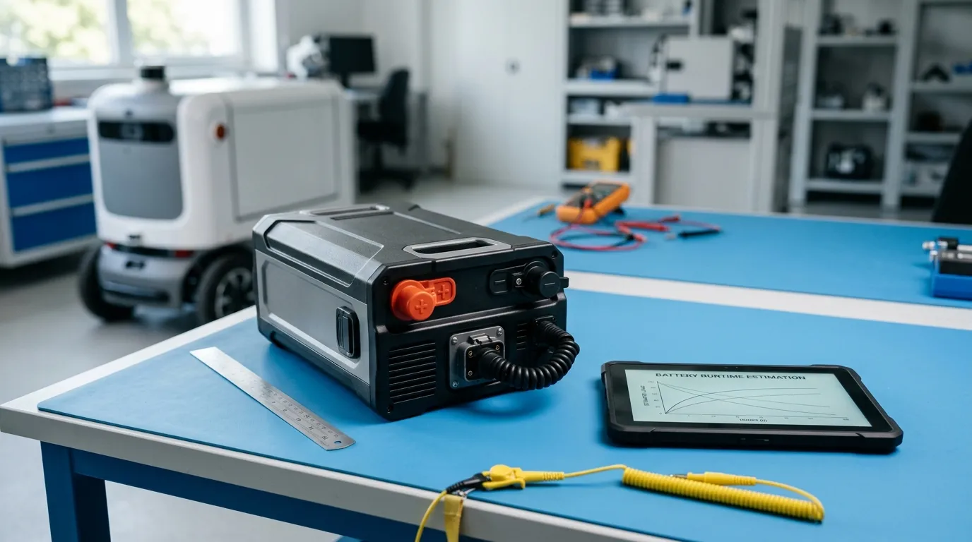
Choosing a rechargeable battery for a delivery robot comes down to two numbers: how much usable energy the pack can deliver and how quickly it can be recharged within your fleet's operating cycle. In practical terms, runtime depends on the pack's usable watt-hours divided by the robot's average power draw during a mission, while charging design depends on chemistry, pack architecture, battery management system (BMS) limits, and whether the robot returns to a dock, plugs into a cable, or swaps a removable pack.
This guide explains how to estimate runtime from real load data, select the right chemistry and pack configuration, design a charging system that supports uptime, and prepare an RFQ that gets you accurate supplier responses. For a broader look at custom options across voltage, cells, connectors, and BMS configurations, see our custom robot battery pack overview.
How to Estimate Runtime for a Delivery Robot
Runtime is not a fixed property of a battery. It is the result of how much energy the pack can deliver under your robot's specific operating conditions. The same pack that runs one robot for six hours may only run another for three, depending on payload, route, speed, and how often the robot accelerates.
Step 1: Determine usable watt-hours
Battery capacity is often stated in amp-hours (Ah), but amp-hours alone do not tell you how much energy is available. Energy in watt-hours (Wh) is the more useful figure because it accounts for voltage.
Usable Wh = nominal voltage × capacity (Ah) × usable depth of discharge
Most lithium-based packs should not be discharged to zero on a regular basis. A typical usable window is 80–90% of rated capacity, but the exact limit depends on the cell chemistry, BMS settings, and how aggressively the pack is cycled. For delivery robots, planning around 80–90% usable energy is a reasonable starting point, with a further reserve for battery aging and cold-weather performance.
Step 2: Measure or estimate average power draw
The robot's average power draw during a mission is the second input. Power in watts (W) can be measured directly with a current logger on the battery output, or estimated by breaking the mission into phases.
Measuring or Estimating the Robot's Average Power
A delivery mission is not a single constant load. It includes several phases with different power demands:
- Acceleration and deceleration — high current peaks for short durations.
- Cruising — steady power draw at operating speed.
- Climbing ramps — higher sustained current.
- Obstacle negotiation — variable current depending on terrain.
- Sensors, computing, and communication — continuous baseline load.
- Idle and waiting — low but significant load if electronics stay active.
- Dock approach and return — moderate load during navigation.
If you have a prototype or an existing robot, log battery current over a representative route that includes payload, terrain, and environmental conditions. If you are still in the design phase, estimate each phase separately and sum the energy contributions.
For comparison, other autonomous service robots face similar load-profile challenges. Our Custom battery for pool cleaning robots page explains how duty cycles differ across autonomous applications.
Step 3: Calculate runtime
Runtime (hours) = usable Wh ÷ average power draw (W)
This is a planning estimate, not a guaranteed specification. Real-world runtime changes with payload, terrain, speed, temperature, battery age, and how deeply the robot is allowed to discharge before returning to charge.
Include a reserve. If the calculated runtime is 5 hours, but the fleet schedule requires a 4-hour shift plus return-to-dock time, a 20–30% energy buffer is prudent. That buffer covers aging, cold weather, heavy payloads, unexpected detours, and BMS cutoffs. A battery that is discharged too close to its limit on every cycle will also age faster.
Step 4: Check peak current and voltage sag
Runtime depends on average power, but the pack must also survive peak currents. During acceleration, climbing, or obstacle negotiation, the robot may draw two to three times its average current for short periods.
Voltage sag occurs when internal resistance causes the pack voltage to drop under load. If the voltage falls below the robot's minimum operating threshold, the system may reset, shut down, or trigger a BMS protection event. This can happen even when the pack still has plenty of energy. Specify both a continuous current rating and a peak current rating with a defined duration (for example, 30 A continuous and 60 A for 10 seconds) so the supplier can select cells and configure the pack accordingly.
Choosing the Delivery-Robot Battery Chemistry
Three chemistries appear most often in delivery-robot battery discussions: lithium-ion (Li-ion), lithium iron phosphate (LiFePO4), and lithium polymer (LiPo). None is universally "best." The right choice depends on weight, volume, charging speed, safety requirements, cycle life, and cost.
| Chemistry | Energy Density | Cycle Life (typical) | Charge Voltage (per cell) | Weight/Volume Impact | Best Fit |
|---|---|---|---|---|---|
| Li-ion (NMC/INR type) | High | Moderate | ~4.2 V | Lower weight for same energy | Robots where runtime and weight are critical |
| LiFePO4 | Lower | Higher | ~3.65 V | Heavier for same energy | Robots where safety and cycle life matter more |
| LiPo (pouch) | High | Moderate | ~4.2 V | Flexible form factor | Space-constrained enclosures |
Li-ion is the common default for delivery robots because it offers high energy density in a compact package. Cylindrical formats such as 18650 and 21700 are widely used because they are readily available, cost-effective, and offer consistent cell quality when properly matched. If the robot has a tight weight budget, Li-ion is usually the starting point.
LiFePO4 is a strong alternative when safety margin and cycle life are more important than weight. It has a lower nominal voltage (about 3.2 V per cell versus 3.6–3.7 V for Li-ion), which means a higher series count may be needed to reach the same pack voltage. It is also heavier for the same energy. For delivery robots that operate in dense pedestrian areas or require very long service life, the trade-off is often worth it.
LiPo/pouch cells offer design flexibility for irregular or thin enclosures. They require careful mechanical protection and typically need a rigid enclosure or support structure. Pouch cells also require more attention to swelling management over the pack's life. If your robot's enclosure is flat, curved, or space-constrained, a LiPo pack may be worth evaluating. Our lipo battery for robotics page covers pouch-cell considerations in more depth.
The chemistry decision should be driven by your robot's payload budget, volume envelope, charging rate, operating temperature, and expected service life — not by a generic preference for one chemistry.
How Chemistry Affects Charging Behavior
Charging design must match the chemistry and the pack's series configuration. Each chemistry has a different maximum charge voltage per cell and a different tolerance for charge current.
- Li-ion and LiPo are typically charged to about 4.2 V per cell using a constant-current/constant-voltage (CC/CV) profile. Higher charge currents are possible with the right cells, but they generate heat and can shorten cycle life.
- LiFePO4 cells charge to about 3.65 V per cell. They generally accept higher charge rates with less thermal stress, but the lower voltage means the pack must have enough series cells to reach the system voltage the robot requires.
The charger must be specified for the pack's exact voltage and current limits. A charger designed for a 14.8 V Li-ion pack (4S) must not be used on a 12.8 V LiFePO4 pack (4S) — the voltage profiles are different. The BMS also plays a role by limiting charge current and terminating charge at the correct voltage. The charger, BMS, and pack must be engineered as one system.
Designing the Battery Pack Architecture
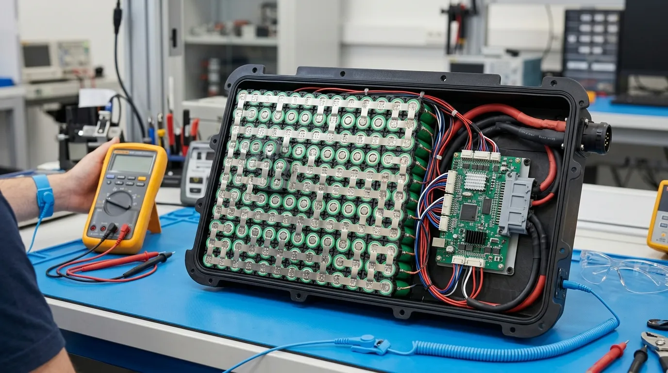
The pack architecture translates your robot's requirements into a specific electrical configuration.
Voltage, Capacity, and Energy
The pack voltage is set by the robot's motor system, electronics, and charger. Series cells determine voltage. A 4S configuration of Li-ion cells produces a nominal voltage around 14.8 V; a 4S LiFePO4 pack produces around 12.8 V. Parallel cells determine capacity and available current. A 4S2P pack has two parallel strings of four series cells, doubling capacity and current capability compared with a 4S1P pack.
Capacity in amp-hours (Ah) tells you how much charge the pack holds. Energy in watt-hours (Wh) tells you how much work the pack can do. To convert between them: Wh = nominal voltage × Ah. A 10 Ah pack at 14.8 V stores 148 Wh. At 12.8 V, the same 10 Ah pack stores only 128 Wh — even though the Ah figure is identical. Always compare packs on energy, not just capacity.
Continuous and Peak Current
The pack must deliver the robot's continuous current without excessive voltage sag or heating. It must also handle peak currents during acceleration and climbing without tripping the BMS.
When you prepare your specification, state both values:
- Continuous current (A) — the current the robot draws for extended periods.
- Peak current (A) with duration (seconds) — the transient current and how long it must be sustained.
C-rate is a related way to express current relative to capacity. A 5 Ah pack at 1C delivers 5 A; at 2C it delivers 10 A. C-rate is useful for comparing cells, but the actual current in amps is what the robot cares about.
Protecting the Pack with a BMS
A battery management system is not optional for a delivery-robot pack. At minimum, the BMS protects against overcharge, over-discharge, overcurrent, short circuit, and extreme temperatures. More advanced BMS functions include:
- Cell balancing — equalizes state of charge across series cells, which is critical as the pack ages.
- Fuel gauge / state of charge (SOC) estimation — gives the robot a reliable remaining-runtime estimate.
- Communication — protocols such as CAN allow the robot and charger to exchange data with the BMS.
A basic PCM (protection circuit module) provides protection but does not communicate or balance. A smart BMS adds monitoring, balancing, and communication. For delivery robots that need to report battery state to a fleet management system, a smart BMS with CAN is the practical choice.
If you are comparing industrial mobile robots to delivery robots, our industrial robot battery pack page explains how AGV and AMR requirements differ.
Mechanical Integration Considerations
The pack must fit the robot's mechanical envelope without compromising safety or serviceability. Key factors include:
- Enclosure — protects cells from impact, dust, and moisture. An IP rating describes the level of protection; it is not the same as "waterproof."
- Connector and wiring — must match the robot's current, polarity, and locking requirements. A connector that is undersized for peak current becomes a heat source.
- Thermal path — cells generate heat during discharge and especially during fast charging. The enclosure must provide a path for heat to escape.
- Mounting — the pack must be secured against vibration and shock. A removable pack needs a connector and mechanical latch designed for repeated insertion and removal.
Specify the available dimensions, weight limit, connector type, and any IP rating requirement in your RFQ.
Designing the Charging System for Fleet Uptime
Charging is not just about plugging in a charger. For a delivery-robot fleet, charging strategy affects uptime, battery life, and operational cost.
| Approach | Description | Uptime Impact | Design Considerations |
|---|---|---|---|
| Cable charging | Robot or operator connects a cable to the pack | Low to medium; requires human action or a robotic arm | Simple, low cost; connector wear; manual intervention |
| Charging dock | Robot navigates to a dock and connects automatically | High; supports frequent top-up | Contact alignment, communications, thermal design, dock cost |
| Battery swapping | Operator replaces a depleted pack with a charged one | Highest; minimal robot downtime | Spare-pack inventory, pack removability, connector durability, safety interlocks |
For a typical delivery robot, the charger must match the pack's series count, maximum charge voltage, and allowed charge current. Charge current is a trade-off: higher current charges faster but generates more heat and can reduce cycle life. The BMS will limit current if the pack is too hot or too cold, which means the charger and BMS must be configured to communicate or at least to terminate charge correctly.
Fast charging is possible with the right cells, BMS design, and thermal management, but it requires the entire system — cells, pack construction, thermal path, charger, and BMS — to be designed for it. It cannot be added to an existing pack by simply increasing charger current.
Charger and Battery Interface Requirements
When you specify the charger, define:
- Output voltage range — must match the pack's charge voltage, not just nominal voltage.
- Output current — must match the BMS charge limits and cell capabilities.
- Charge termination — how charge stops (BMS command, charger cutoff, or communication).
- Connector — must match the pack connector and support the charge current.
- Interlock — charge should not start unless the connector is fully seated and the robot is in a safe state.
For battery-swapping systems, the same interface requirements apply, but the pack's connector must also tolerate repeated mating cycles and be keyed to prevent incorrect insertion.
Validating the Battery Before Deployment
A battery specification on paper is not enough. The pack must demonstrate that it meets the specification under defined test conditions. When you evaluate a supplier, request evidence for the following:
| Test or Document | What It Verifies | Scope Limitation |
|---|---|---|
| Datasheet / TDS | Rated voltage, capacity, energy, current, dimensions, weight | Applies to the named model only |
| Capacity test | Delivered capacity at a stated discharge rate and temperature | Set by test conditions; not a universal figure |
| Continuous and peak current test | Ability to deliver rated current without excessive voltage drop or shutdown | Must specify current and duration |
| Vibration / drop / shock test | Mechanical durability for robot operation | Application-specific; define the test standard and level |
| Cycle test | Capacity retention after a defined number of cycles | Requires specified rate, depth of discharge, temperature, and retention threshold |
| SDS / MSDS | Hazard communication for handling and transport | Not a product-safety certification |
| UN38.3 test summary | Transport-safety testing for lithium batteries | Applies to the tested product/batch; required for air and most ground transport |
A common confusion is treating a UN38.3 test summary as a product-safety certification. It is not. UN38.3 is a transport requirement. It demonstrates that a battery has passed a defined series of tests for transporting lithium cells and batteries, as explained by the U.S. Department of Transportation's Pipeline and Hazardous Materials Safety Administration (PHMSA) in its guidance on lithium battery test summaries: PHMSA Lithium Battery Test Summaries.
Separately, IEC/UL product-safety testing may apply to a defined model and standard scope, but it must be verified per product, not assumed from a company-level certificate. If the supplier provides an IEC or UL report, confirm that it covers the exact model and standard you require.
Preparing the Delivery-Robot Battery RFQ

A well-prepared RFQ is the difference between a useful supplier response and a generic quote. Convert your design decisions into a specification that the supplier can evaluate for cell selection, S/P configuration, BMS, mechanical design, and documentation.
Include at minimum:
- System voltage — nominal and maximum charge voltage.
- Rated capacity (Ah) and energy (Wh).
- Continuous current (A).
- Peak current (A) and duration (seconds).
- Operating temperature range — charge, discharge, and storage separately.
- Mechanical envelope — dimensions, weight, connector type, mounting method.
- BMS requirements — protection features, balancing, fuel gauge, communication protocol.
- Charging requirements — charger output, charge current target, charge time.
- Environmental protection — IP rating if required.
- Documentation — datasheet, test reports, SDS, UN38.3 test summary.
- Validation plan — which tests must be performed and with what acceptance criteria.
- Production quality — traceability, change control, inspection, and warranty terms.
At Gloflux, a typical custom robot battery project starts with a requirements discussion covering voltage, cell format, connector, BMS, and application environment. Because every delivery robot has a different load profile, the specification is developed around your robot's actual operating conditions rather than a generic template.
Common Mistakes to Avoid When Specifying a Delivery-Robot Battery
- Confusing capacity with runtime. A higher Ah rating does not guarantee longer runtime if voltage or usable SOC is lower. Compare on usable Wh and average power.
- Ignoring peak current. A pack sized for average power may shut down during acceleration or climbing.
- Underestimating voltage sag. Internal resistance plus high current can drop pack voltage below the robot's operating threshold even with energy remaining.
- Choosing a charger that mismatches the pack. Voltage, current, and termination must match the chemistry and BMS.
- Ignoring temperature extremes. Cold reduces available capacity and increases internal resistance; heat accelerates aging.
- Overlooking usable SOC. Discharging to zero on every cycle shortens life and risks BMS shutdown.
- Treating UN38.3 as product certification. It is a transport requirement, not a safety certification.
A rechargeable battery for a delivery robot is not an off-the-shelf accessory. It is an engineered subsystem that must match the robot's load profile, mechanical constraints, charging infrastructure, and fleet operations. When the specification is built around real runtime and charging data, the result is a pack that delivers predictable uptime — and an RFQ that suppliers can respond to with confidence.
Talk to the Manufacturer
Resources & Insights
High Capacity Lithium Battery for Wearables: High-Voltage LiPo Cell Design
2026-10-19
Cylindrical Battery Packs for Laptops: 2S vs 3S vs 4S Battery Design
2026-10-19
Stage Lighting Battery Pack: Prevent Voltage Drop & LED Flicker
2026-10-19

Best Rechargeable Batteries for Smart Devices: Performance, Safety, and Selection Guide
2026-10-19


